VI - Changing the old extruder of my Rapman by a standard extruder (E3D V6 J-head)
Hello everyone.
A few days ago, doing maintenance to the hot-end, I broke the thermistor.
What a problem ... 200k thermistors are rare and only available online. And I was already bored of looking for alternatives for the fire cement that groups all the heating components, as well as the whole process of winding the resistance, setting, checking, etc. So I decided not to continue fighting with such an obsolete and impractical system and change it better by a standard E3D V6 J-head aluminum extruder, which is now available in the robotics stores or online stores for only US $ 6.99. All a bargain, and that allows to replace future resistance, thermistor and nozzle, quickly and with basic tools.
https://www.aliexpress.com/wholesale?catId=0&initiative_id=SB_20180428092044&SearchText=extruder+E3D+V6+J-head
Another great advantage is that when operating with 12 volts, we can reuse the original power source of the printer and connect the fans directly to the board.

1. The "throat" that connects the heatsink and the heating block is internally coated with PTFE (high temperature nylon) to the nozzle. What guarantees that the filament does not receive much heat inside the extruder, softens and clogs at some point (which is a tragedy for all the disarmament involved).
2. The extruder has a coupling in the upper part that will allow us to adapt the whole system without many stumbles, reusing some original components of the Rapman.
As we are adapting a sophisticated extrusion system to an old equipment, it is convenient to read these two articles from the manufacturer of the extruder first because we must consider the basic indications of assembly of the new system, especially in relation to the torque that is given to the threads as well as the insulation of heat by the thermal paste:
https://wiki.e3d-online.com/E3D-v6_Assembly
https://wiki.e3d-online.com/E3D-v6_Troubleshooting
The thermistor settings in the firmware and the "PID tuning" that are mentioned will be described after assembly.

Relative size of the original extruder vs. E3D V6 Bowden
-----------------------------------
Let's look at the steps necessary to replace the entire heating and extrusion system.
1. We must polish the triangular base of the old hot-end, to be able to place the new fan and its support, using a steel file and abrasive paper to round the edges:

2. As the new extruder consists of several pieces that are screwed together, we separate the dissipator and then reassemble it in the triangular base, as indicated below.
DO NOT FORGET: the torque in the "throat" must be soft and firm, so they do not break it. And the thermal paste is absolutely necessary in the M7 thread (the longest and widest):

Throat with threads M7 y M6
A technical detail: I also removed the top black cap -which has an internal toothed metal ring that prevents retraction of the filament-, because it can cause difficulties in printing. I kept the steel coupling (right end in the image):

The washers are not necessary, then I removed them in the final assembly.
As we can see, the hexagonal columns are short. This space must be adjusted with screws because here the fan support is placed and there should be an advantage for the assembly of the new system in the Rapman printer.
We add some longer screws (in my case, one inch) to be able to integrate the upper part of the old extruder, composed of MDF and acrylic. We take as a guide a piece of 3mm filament that we are going to slide to the nozzle, so that the reused components are aligned and we verify that everything is well assembled and compact.
THE SET CAN NOT BE FEEBLE. IT MUST RIGID.


Remember the screw that drives the Z-axis endstop? (the one in the upper right part of the previous image). We must change it for another longer (3.5 - 4 inches) preferably of the same characteristics, because the new hotend is of a larger size (above, the original and below, the replacement):

To give greater rigidity to the set, and that the extruder is not tilted to the side (because there is tension in only 2 points of the base) I placed a piece of wire 20 gauge at the end where the fan goes and I stressed it against the screw "loose" until the extruder was aligned. It does not look very aesthetic but it is functional. If anyone has a more aesthetic and functional solution, welcome a technical contribution.

4. We assemble the extruder in the print carriage:

Note that the thermistor and resistance wires should be at the free end. And if we place the fan and its support, it remains like this (completely perpendicular to the printing plane):

5. And the cables, how do they join the board? It is a simple task, but it requires a lot of care. The upper ends of the cables that are in the conductor tube (gray for the resistance and violets for the thermistor) are joined with the ends of the new cables and pulled by the lower end:


If the old fan cables are inside the conductive tube, excellent. If they are not, we must slide 2 meters of filament through the tube -to serve as a guide- and join the cables at the top, then pull the filament from below (if you have to channel them, this is the moment):

Once we have the cables ready, we cut them to size, we put the connectors on the ends and connect them to the board. By having a 12 volt power source, we can connect the fans directly to the board, like this:

1. Extruder fan

2. Pololu drivers fan
-----------------------------------
FIRMWARE
As we completely change the heating system, we must reconfigure the temperature in Marlin, placing the code that corresponds to the thermistor reference (in my case it is code 11, since it complies with the NTC 3950 standard, verify the reference with the seller and match the code in the section THERMAL SETTINGS).
Configuration.h:
#define TEMP_SENSOR_0 11 ;(or the one that corresponds with your thermistor)
For safety, it is highly recommended to set the minimum temperature in Marlin to detect incorrect wiring:
#define HEATER_0_MINTEMP 5
Compile and upload the corrected firmware to the Arduino board.
-----------------------------------
PID TUNING
Turn on the printer and connect it to the computer through the port that Arduino brings.
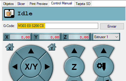
Run on Repetier the gcode M303 to fine-tune the temperature self-tuning system that Marlin supports. For example, M303 E0 S200 C8 where E indicates the extruder, S the reference temperature and C the number of temperature cycles to be performed in the test.
After a few minutes, Repetier gives you some results ending with the line:
PID Autotune finished ! Place the Kp, Ki and Kd constants in the configuration.h
You can review Thomas Sanladerer's video guide for more information:
https://www.youtube.com/watch?v=APzJfYAgFkQ
My values with the NTC 3950 thermistor were:
Kp: 13.68
Ki: 0.78
Kd: 59.97
You could take them as a reference to edit them in Marlin:
#define DEFAULT_Kp 13.68
#define DEFAULT_Ki 0.78
#define DEFAULT_Kd 59.97
Or perform the PID Tuning for your thermistor according to the described video.
-----------------------------------
You can make the final adjustments as described in the article that we mentioned at the beginning:
https://wiki.e3d-online.com/E3D-v6_Assembly
If once the printer is cold, the temperature that appears on the screen corresponds approximately to your ambient temperature, it is almost certain that you are ready. If you have how to measure the heating temperatures for PLA and ABS, check them and do some printing tests.
Remember to first adjust the screw that drives the Z axis endstop, so you do not damage the new extruder.
The heating of this new extruder is super-fast, in seconds, it has a stable temperature curve and the impressions preserve or improve the quality that we had. If the assembly and configuration were correct, I assure you that you will not miss the old extruder.
NOTE: in my heat transfer tests on the heatsink, I found a constant temperature of 60ºC when I placed the hotend at 240ºC. I placed an additional fan on the other end of the heatsink and the temperature dropped to 45ºC. The colder the extruder is, better, thus preventing the annoying blockages of the filament.
Consider placing an additional fan by electrical bypass of the other fan or with independent wiring.
Welcome your observations.
Good luck!
-----------------------------------
No comments:
Post a Comment